Standard Dimensions
4"–24"
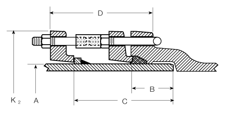
| Size (in.) | A Outside Diameter (in.) |
B Socket Depth (in.) |
C Plain End to Gland (in.) |
K2 Gland OD (in.) |
Bolts or Studs No. |
Tee- Head Bolt (in.) |
Stud (in.) |
MJCJE & MJCJE Minimum Laying Length (ft.) |
|---|---|---|---|---|---|---|---|---|
| 4 | 4.8 | 2.50 | 6.34 | 9.12 | 4 | 3/4 x 4 |
3/4 × 3 1/2 | 2’-3" |
| 6 | 6.9 | 2.50 | 6.50 | 11.12 | 6 | 3/4 x 4 |
3/4 × 3 1/2 | 2’-3" |
| 8 | 9.05 | 2.50 | 6.64 | 13.37 | 6 | 3/4 × 4 1/2 | 3/4 × 3 1/2 | 2’-3" |
| 10 | 11.10 | 2.50 | 6.71 | 15.69 | 8 | 3/4 × 4 1/2 | 3/4 × 3 1/2 | 2’-3" |
| 12 | 13.20 | 2.50 | 6.77 | 17.94 | 8 | 3/4 × 4 1/2 | 3/4 × 3 1/2 | 2’-3" |
| 14 | 15.30 | 3.50 | 8.88 | 20.31 | 10 | 3/4 x 5 |
3/4 x 5 |
2’-9" |
| 16 | 17.40 | 3.50 | 8.88 | 22.56 | 12 | 3/4 x 5 |
3/4 x 5 |
2’-9" |
| 18 | 19.50 | 3.50 | 8.88 | 24.83 | 12 | 3/4 x 5 |
3/4 x 5 |
3’-0" |
| 20 | 21.60 | 3.50 | 8.88 | 27.08 | 14 | 3/4 × 6 | 3/4 x 5 |
3’-0" |
| 24 | 25.80 | 3.50 | 8.88 | 31.58 | 16 | 3/4 × 6 | 3/4 x 5 |
3’-0" |
30"–48"
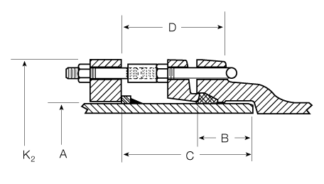
| Size (in.) |
A Outside Diameter (in.) |
B Socket Depth (in.) |
C Plain End to Gland (in.) |
K2 Gland OD (in.) |
Bolts or Studs No. | Tee-Head Bolt (in.) |
Stud (in.) |
MJCJE & MJCJE Minimum Laying Length (ft.) |
||
|---|---|---|---|---|---|---|---|---|---|---|
| 30 | 32.00 | 4.00 | 10.88 | 39.12 | 20 | 1 × 7 | 1 × 6 | 3’-6" | ||
| 36 | 38.30 | 4.00 | 10.88 | 46.00 | 24 | 1 × 7 | 1 × 6 | 3’-6" | ||
| 42 | 44.50 | 4.00 | 11.63 | 53.12 | 28 | 1 1/4 × 7 | 1 1/4 × 7 | 4’-0" | ||
| 48 | 50.80 | 4.00 | 11.63 | 60.00 | 32 | 1 1/4 × 7 | 1 1/4 × 7 | 4’-0" |
Coupling Gland Joints
Coupling gland ends (CGE) are provided as a method of restraining across couplings. Restraining glands can be furnished of steel or ductile iron at the manufacturer’s option. Alloy steel rods are furnished, and the number of rods furnished for each pipe size allows the joint to be rated at 250 psi water working pressure.
The joint is designed to allow “drop-in” installation. This means that, based on popular short coupling lengths, the coupling will normally clear the end of the pipe if it is pushed all of the way to the gland on that piece of pipe. Note: AMERICAN does not furnish the couplings used with this joint; therefore, the user should check coupling pressure rating, length, and diameter dimensions used for appropriate clearances to make sure they are compatible with the joint before ordering.
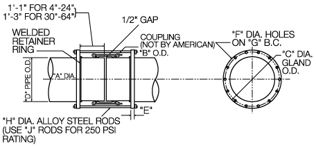
| A (in.) |
B Maximum (in.) |
C (in.) |
D Pipe OD (in.) |
E (in.) |
F B.H. Dia. (in.) |
G B.C. (in.) |
H Tie Rod ø (in.) |
J No. Rods |
Tie Rod Length (in.) |
|---|---|---|---|---|---|---|---|---|---|
| 4 | 9.00 | 11.50 | 4.80 | 1.00 | 7/8 | 9.88 | 3/4 | 4 | 31 1/2 |
| 6 | 11.00 | 13.50 | 6.90 | 1.00 | 7/8 | 11.88 | 3/4 | 4 | 31 1/2 |
| 8 | 13.06 | 15.63 | 9.05 | 1.00 | 7/8 | 13.94 | 3/4 | 4 | 31 1/2 |
| 10 | 15.81 | 18.37 | 11.10 | 1.00 | 7/8 | 16.69 | 3/4 | 4 | 31 1/2 |
| 12 | 18.06 | 20.63 | 13.20 | 1.00 | 7/8 | 18.94 | 3/4 | 6 | 31 1/2 |
| 14 | 19.31 | 23.00 | 15.30 | 1.50 | 7/8 | 21.32 | 3/4 | 10 | 31 1/2 |
| 16 | 21.38 | 24.63 | 17.40 | 2.00 | 7/8 | 23.01 | 3/4 | 12 | 31 1/2 |
| 18 | 23.5 | 27.00 | 19.50 | 2.00 | 7/8 | 25.38 | 3/4 | 12 | 31 1/2 |
| 20 | 25.63 | 29.13 | 21.60 | 2.00 | 7/8 | 27.51 | 3/4 | 14 | 31 1/2 |
| 24 | 29.19 | 33.38 | 25.80 | 2.00 | 7/8 | 31.69 | 3/4 | 16 | 31 1/2 |
| 30 | 37.00 | 40.11 | 32.00 | 2.25 | 1 1/8 | 38.25 | 1 | 20 | 39 1/2 |
| 36 | 43.31 | 46.30 | 38.30 | 2.44 | 1 1/8 | 44.56 | 1 | 24 | 39 1/2 |
| 42 | 49.50 | 53.12 | 44.50 | 2.62 | 1 3/8 | 51.00 | 1 1/4 | 28 | 41 1/2 |
| 48 | 55.81 | 60.00 | 50.80 | 2.81 | 1 3/8 | 57.50 | 1 1/4 | 32 | 41 1/2 |
| 54 | 62.57 | 66.88 | 57.56 | 3.00 | 1 3/8 | 64.38 | 1 1/4 | 36 | 41 1/2 |
| 60 | 66.41 | 73.00 | 61.61 | 3.12 | 1 3/4 | 69.25 | 1 1/2 | 26 | 42 |
| 64 | 70.47 | 80.00 | 65.67 | 3.38 | 1 3/4 | 76.00 | 1 1/2 | 26 | 42 |
Note: If limited flexibility or expansion/contraction capabilities are important in the application.