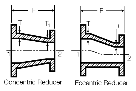
Bell Reducers
The dimensions and weights of concentric and eccentric reducers are normally the same. If the order does not specify an eccentric reducer, then a concentric reducer will be furnished. Eccentric reducers are available in most of the sizes listed.
Numerals on cuts indicate standard order of specifying size of fitting.
| Size (in.) |
Pressure Rating (psi) |
Dimensions in Inches | Weight (lbs.) |
|||
|---|---|---|---|---|---|---|
| Large End |
Small End |
T | T 1 | F | ||
| 6 | 4 | 250 | 0.55 | 0.52 | 9 | 45 |
| 8 | 4 | 250 | 0.6 | 0.52 | 11 | 65 |
| 8 | 6 | 250 | 0.6 | 0.55 | 11 | 75 |
| 10 | 4 | 250 | 0.68 | 0.52 | 12 | 85 |
| 10 | 6 | 250 | 0.68 | 0.55 | 12 | 95 |
| 10 | 8 | 250 | 0.68 | 0.6 | 12 | 110 |
| 12 | 4 | 250 | 0.75 | 0.52 | 14 | 120 |
| 12 | 6 | 250 | 0.75 | 0.55 | 14 | 130 |
| 12 | 8 | 250 | 0.75 | 0.6 | 14 | 145 |
| 12 | 10 | 250 | 0.75 | 0.68 | 14 | 165 |
| 14 | 6 | 250 | 0.66 | 0.55 | 16 | 155 |
| 14 | 8 | 250 | 0.66 | 0.6 | 16 | 170 |
| 14 | 10 | 250 | 0.66 | 0.68 | 16 | 195 |
| 14 | 12 | 250 | 0.66 | 0.75 | 16 | 225 |
| 16 | 6 | 250 | 0.7 | 0.55 | 18 | 190 |
| 16 | 8 | 250 | 0.7 | 0.6 | 18 | 210 |
| 16 | 10 | 250 | 0.7 | 0.68 | 18 | 235 |
| 16 | 12 | 250 | 0.7 | 0.75 | 18 | 265 |
| 16 | 14 | 250 | 0.7 | 0.66 | 18 | 280 |
| 18 | 6 | 250 | 0.75 | 0.55 | 19 | 220 |
| 18 | 8 | 250 | 0.75 | 0.6 | 19 | 240 |
| 18 | 10 | 250 | 0.75 | 0.68 | 19 | 265 |
| 18 | 12 | 250 | 0.75 | 0.75 | 19 | 295 |
| 18 | 14 | 250 | 0.75 | 0.66 | 19 | 305 |
| 18 | 16 | 250 | 0.75 | 0.7 | 19 | 335 |
| 20 | 6 | 250 | 0.8 | 0.55 | 20 | 265 |
| 20 | 8 | 250 | 0.8 | 0.6 | 20 | 285 |
| 20 | 10 | 250 | 0.8 | 0.68 | 20 | 310 |
| 20 | 12 | 250 | 0.8 | 0.75 | 20 | 345 |
| 20 | 14 | 250 | 0.8 | 0.66 | 20 | 355 |
| 20 | 16 | 250 | 0.8 | 0.7 | 20 | 385 |
| 20 | 18 | 250 | 0.8 | 0.75 | 20 | 410 |
| 24 | 8 | 250 | 0.89 | 0.6 | 24 | 410 |
| 24 | 10 | 250 | 0.89 | 0.68 | 24 | 440 |
| 24 | 12 | 250 | 0.89 | 0.75 | 24 | 480 |
| 24 | 14 | 250 | 0.89 | 0.66 | 24 | 490 |
| 24 | 16 | 250 | 0.89 | 0.7 | 24 | 525 |
| 24 | 18 | 250 | 0.89 | 0.75 | 24 | 550 |
| 24 | 20 | 250 | 0.89 | 0.8 | 24 | 595 |
| 30 | 12 | 250 | 1.03 | 0.75 | 30 | 730 |
| 30 | 16 | 250 | 1.03 | 0.66 | 30 | 735 |
| 30 | 18 | 250 | 1.03 | 0.75 | 30 | 815 |
| 30 | 20 | 250 | 1.03 | 0.8 | 30 | 865 |
| 30 | 24 | 250 | 1.03 | 0.89 | 30 | 965 |
| 36 | 16 | 250 | 1.15 | 0.7 | 36 | 1115 |
| 36 | 18 | 250 | 1.15 | 0.75 | 36 | 1160 |
| 36 | 20 | 250 | 1.15 | 0.8 | 36 | 1225 |
| 36 | 24 | 250 | 1.15 | 0.89 | 36 | 1340 |
| 36 | 30 | 250 | 1.15 | 1.03 | 36 | 1550 |
| 42 | 24 | 250 | 1.28 | 0.89 | 42 | 1810 |
| 42 | 30 | 250 | 1.28 | 1.03 | 42 | 2060 |
| 42 | 36 | 250 | 1.28 | 1.15 | 42 | 2345 |
| 48 | 30 | 250 | 1.42 | 1.03 | 48 | 2615 |
| 48 | 36 | 250 | 1.42 | 1.15 | 48 | 2940 |
| 48 | 42 | 250 | 1.42 | 1.28 | 48 | 3320 |
| 54 | 42 | 2502 | 0.9 | 1.25 | 25 | 2025 |
| 54 | 48 | 2502 | 0.9 | 1.4 | 18 | 1915 |
| 60 | 48 | 2502 | 0.94 | 1.4 | 20 | 2360 |
| 60 | 54 | 2502 | 0.94 | 0.9 | 15 | 2055 |
| 64 | 54 | 2502 | 0.99 | 0.9 | 18 | 2695 |
| 64 | 60 | 2502 | 0.99 | 0.94 | 17 | 2980 |
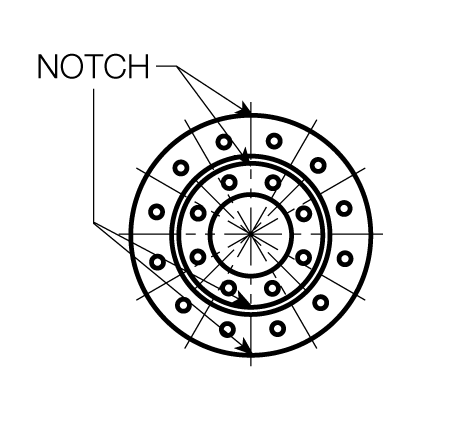
CAUTION: When Installing Flanged Reducers:
The two flanges on most reducers have a different number of bolt holes, and all adjacent bolt holes do not straddle a centerline common to both flanges.
The centerline of the reducer is marked by notches on the circumference of each flange, and installation must be made in reference to this centerline. This would also be applicable with most reducing flanges and reducing flange fillers. Failure to assemble with the centerline at 12 o’clock will result in downstream equipment or bends not bolting correctly.