Deflection and Offset
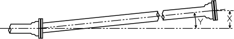
The liberal allowable deflection in the Fastite joint facilitates the installation of pipelines that include sweeping horizontal or vertical curves without the use of fittings.
For optimum assembly, the joints should be assembled with the pipe in reasonably straight alignment. After joint assembly, the pipe may be deflected up to the maximum shown. Offset distances and radii are based on nominal lengths shown.
| Size (in.) | Nominal Laying Length (ft.) |
Standard Bell | ||
|---|---|---|---|---|
| X Offset per Nominal Length (in.) |
Y Deflection Angle |
Radius of Curve1 (ft.) |
||
| 4 | 20 | 21 | 5° | 206 |
| 6 | 20 | 21 | 5° | 230 |
| 8 | 20 | 21 | 5° | 230 |
| 10 | 20 | 21 | 5° | 230 |
| 12 | 20 | 21 | 5° | 230 |
| 14 | 20 | 17 | 4° | 286 |
| 16 | 20 | 12 | 3° | 381 |
| 18 | 20 | 12 | 3° | 381 |
| 20 | 20 | 12 | 3° | 381 |
| 24 | 20 | 12 | 3° | 381 |
| 30 | 20 | 10 | 2 1/2° | 458 |
1) Approximate radius of curve produced by a succession of nominal lengths of pipe fully deflected.
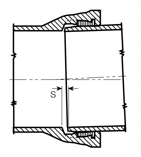
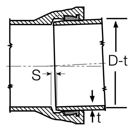
Maximum Allowable Separation
Maximum allowable separation in standard bell pipe is approximately equal to the median pipe diameter in inches times the sine of the deflection angle. This is provided for information only and should not be used to determine precise joint deflection.
| Size (in.) | S Separation (in.) |
|---|---|
| 4 | 3/8 |
| 6 | 9/16 |
| 8 | 3/4 |
| 10 | 15/16 |
| 12 | 1 1/8 |
| 14 | 1 5/16 |
| 16 | 1 1/2 |
| 18 | 1 5/8 |
| 20 | 1 7/8 |
| 24 | 2 1/4 |
| 30 | 2 3/4 |