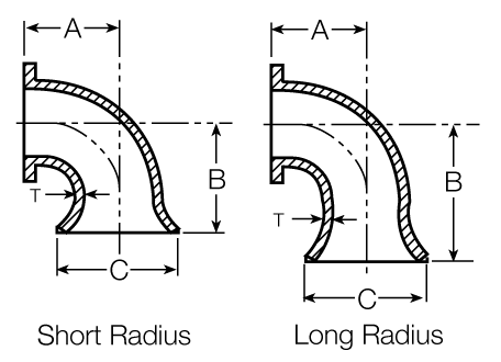
Flange and Flare 90° Bends
| Size (in.) |
T (in.) |
C (in.) |
Short Radius | Long Radius | ||||
|---|---|---|---|---|---|---|---|---|
| A (in.) |
B (in.) |
Weight (lbs.) |
A (in.) |
B (in.) |
Weight (lbs.) |
|||
| 4 | 0.52 | 9.00 | 6.50 | 12.00 | 45 | 9.00 | 14.50 | 50 |
| 6 | 0.55 | 11.00 | 8.00 | 12.00 | 75 | 11.50 | 15.50 | 90 |
| 8 | 0.60 | 13.50 | 9.00 | 14.00 | 120 | 14.00 | 19.00 | 155 |
| 10 | 0.68 | 16.00 | 11.00 | 17.00 | 195 | 16.50 | 22.50 | 250 |
| 12 | 0.75 | 19.00 | 12.00 | 18.00 | 275 | 19.00 | 25.00 | 375 |
| 14 | 0.66 | 21.00 | 14.00 | 21.50 | 310 | 21.50 | 29.00 | 400 |
| 16 | 0.70 | 23.50 | 15.00 | 23.00 | 395 | 24.00 | 32.00 | 530 |
| 18 | 0.75 | 25.00 | 16.50 | 25.00 | 495 | 26.50 | 35.00 | 675 |
| 20 | 0.80 | 27.50 | 18.00 | 27.00 | 630 | 29.00 | 38.00 | 865 |
| 24 | 0.89 | 32.00 | 22.00 | 32.50 | 995 | 34.00 | 44.50 | 1335 |
| 30 | 1.03 | 38.75 | 25.00 | 36.00 | 1970 | 41.50 | 48.50 | 2190 |
| 36 | 1.15 | 46.00 | 28.00 | 38.00 | 2730 | 49.00 | 56.00 | 3465 |
| 42 | 1.28 | 53.00 | 31.00 | 35.00 | 3200 | 56.50 | 63.50 | 5150 |
| 48 | 1.42 | 59.50 | 34.00 | 46.00 | 5235 | 64.00 | 71.00 | 6725 |
1.) 54" and 60" castings have wall thicknesses that are per AWWA C153. All other wall thicknesses are per C100. See Thrust Collars.
2.) Contact AMERICAN for 64" Flare dimensions.
Since above fittings are not included in AWWA C110, A, B, and C dimensions above should be specified on engineering drawings.
Other joints can be furnished in lieu of flanges in some sizes.