Weights
| Size (in.) |
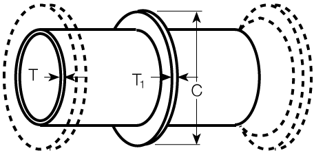
T 1 Thickness in. |
C Diameter in. |
Weight lb |
Allowable Load Per Collar T lbs1 |
|---|---|---|---|---|
| 4 | 0.25 | 6.80 | 1 | 4500 |
| 6 | 0.25 | 8.90 | 2 | 9300 |
| 8 | 0.25 | 11.05 | 2 | 16000 |
| 10 | 0.25 | 13.10 | 3 | 24000 |
| 12 | 0.25 | 15.20 | 3 | 34000 |
| 14 | 0.25 | 17.30 | 5 | 46000 |
| 16 | 0.25 | 19.40 | 6 | 59000 |
| 18 | 0.38 | 22.50 | 15 | 75000 |
| 20 | 0.38 | 24.60 | 11 | 92000 |
| 24 | 0.38 | 28.80 | 13 | 130000 |
| 30 | 0.50 | 36.00 | 29 | 200000 |
| 36 | 0.50 | 42.30 | 35 | 290000 |
| 42 | 0.75 | 50.75 | 98 | 390000 |
| 48 | 0.75 | 57.05 | 111 | 510000 |
| 54 | 1.00 | 66.06 | 231 | 650000 |
| 60 | 1.00 | 70.11 | 246 | 745000 |
| 64 | 1.00 | 74.17 | 261 | 847000 |
1.) These values are based on dead-end thrust due to 250 psi internal pressure. For higher allowable loads or pressures, contact AMERICAN. (See also the figure above Table No. 9–11, for use of thrust collars, e.g., in some buried systems where other types of concrete thrust blocks cannot be used.)
Welded-on thrust collars are normally fabricated from steel. If collars are to be furnished of annealed ductile iron, dimensions and weights are the same as those found in Wall Collar Weights.
Collars may be angled and/or rotated from top dead center (TDC).