Standard Dimensions
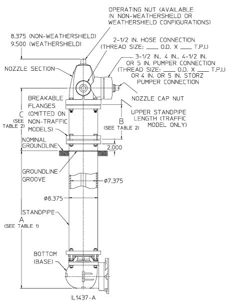
Table 1
| Bury Depth1 | DIM. A | Rod Length | ||
|---|---|---|---|---|
|
With Flanged Mech.Joint or TYTON®3 Bottom |
With Vertical Entry Bottom2 |
Traffic Model (Lower Rod Length) |
Non-Traffic Model | |
| FT – IN. | FT – IN. | FT – IN. | FT – IN. | FT – IN. |
| 3 – 0 | 3 – 0.750 | 3 – 3.125 | 2 – 9.312 | 4 – 6.062 |
| 3 – 6 | 3 – 6.750 | 3 – 9.125 | 3 – 3.312 | 5 – 0.062 |
| 4 – 0 | 4 – 0.750 | 4 – 3.125 | 3 – 9.312 | 5 – 6.062 |
| 4 – 6 | 4 – 6.750 | 4 – 9.125 | 4 – 3.312 | 6 – 0.062 |
| 5 – 0 | 5 – 0.750 | 5 – 3.125 | 4 – 9.312 | 6 – 6.062 |
| 5 – 6 | 5 – 6.750 | 5 – 9.125 | 5 – 3.312 | 7 – 0.062 |
| 6 – 0 | 6 – 0.750 | 6 – 3.125 | 5 – 9.312 | 7 – 6.062 |
| 6 – 6 | 6 – 6.750 | 6 – 9.125 | 6 – 3.312 | 8 – 0.062 |
| 7 – 0 | 7 – 0.750 | 7 – 3.125 | 6 – 9.312 | 8 – 6.062 |
| 7 – 6 | 7 – 6.750 | 7 – 9.125 | 7 – 3.312 | 9 – 0.062 |
| 8 – 0 | 8 – 0.750 | 8 – 3.125 | 7 – 9.312 | 9 – 6.062 |
| 8 – 6 | 8 – 6.750 | 8 – 9.125 | 8 – 3.312 | 10 – 0.062 |
| 9 – 0 | 9 – 0.750 | 9 – 3.125 | 8 – 9.312 | 10 – 6.062 |
| 9 – 6 | 9 – 6.750 | 9 – 9.125 | 9 – 3.312 | 11 – 0.062 |
| 10 – 0 | 10 – 0.750 | 10 – 3.125 | 9 – 9.312 | 11 – 6.062 |
1.) Bury depth is the nominal distance from groundline to bottom of connecting pipe. 1’6” through 11’ 6” bury depths are available.
2.) For vertical entry bottoms, bury depth is measured to the face of the inlet flange. See Optional Bases.
3.) TYTON® is a registered trademark of United States Pipe and Foundry Co., LLC.
Table 2
| DIM. B Upper Standpipe Length (Traffic Models Only) |
DIM. C Nozzle Elevation Above Groundline |
|
|---|---|---|
| Traffic Model (WB67-250) | Non-Traffic Model (W67-250) | |
| 10 IN. | 18 IN. | 18 IN. |
| 16 IN. | 24 IN. | |
| 22 IN. | 30 IN. | |
| 28 IN. | 36 IN. | |
| 34 IN. | 42 IN. | |
NOTES
- 250 psig rated working pressure.
- Meets or exceeds all requirements of AWWA C502.
- May be ordered in configurations that are UL Listed and FM Approved.