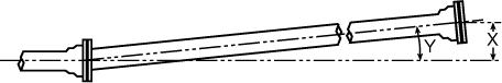
Deflection and Offset
For optimum assembly, the joints should be assembled with the pipe in reasonably straight alignment. Joint deflection to the maximum shown may be made after assembly but before tightening bolts. Offset distances are based on nominal lengths shown. 14” to 48” Mechanical joints are provided on fittings and valves only.

| Size (in.) | Nominal Laying Length (ft.) | Maximum Recommended Deflection | ||
|---|---|---|---|---|
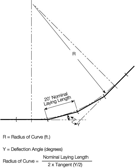
| X Offset1 per Nominal Length (in.) | Y Deflection Angle | Radius of Curve1 (ft.) | ||
| 4 | 20 | 34 | 8°-18’ | 124 |
| 6 | 20 | 30 | 7°-07’ | 160 |
| 8 | 20 | 22 | 5°-21’ | 220 |
| 10 | 20 | 22 | 5°-21’ | 220 |
| 12 | 20 | 22 | 5°-21’ | 220 |
| 14 | - | - | 3°-35’ | - |
| 16 | - | - | 3°-35’ | - |
| 18 | - | - | 3°-00’ | - |
| 20 | - | - | 3°-00’ | - |
| 24 | - | - | 2°-23’ | - |
| 30 | - | - | 2°-23’ | - |
| 36 | - | - | 2°-05’ | - |
| 42 | - | - | 2°-00’ | - |
| 48 | - | - | 2°-00’ | - |
1) Offset distances are based on 20’ lengths.
2) Approximate radius of curve produced by a succession of nominal lengths of pipe fully deflected. A shorter radius can be obtained using shorter pipes.

| Size (in.) |
S Separation (in.) |
|---|---|
| 24 | 1 |
| 30 | 1 1/4 |
| 36 | 1 3/8 |
| 42 | 1 1/2 |
| 48 | 1 3/4 |