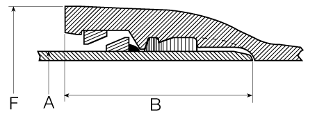
Deflection and Offset
4"–12"
| Size (in.) |
Working Pressure1 (psi) |
Nominal Laying Length2 (ft) |
Allowable Deflection (degrees) |
Offset per 20’ Length (in.) |
Radius of Curve3 (ft.) |
|---|---|---|---|---|---|
| 4 | 350 | 20 | 5 | 21 | 230 |
| 6 | 350 | 20 | 5 | 21 | 230 |
| 8 | 350 | 20 | 5 | 21 | 230 |
| 10 | 350 | 20 | 5 | 21 | 230 |
| 12 | 350 | 20 | 5 | 21 | 230 |
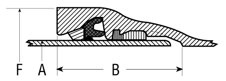
14"–54"
| Size (in.) |
Working Pressure1 (psi) |
Nominal Laying Length2 (ft) |
Allowable Deflection (degrees) |
Offset per 20’ Length (in.) |
Radius of Curve3 (ft.) |
|---|---|---|---|---|---|
| 14 | 350 | 20 | 4 | 17 | 285 |
| 16 | 350 | 20 | 3 3/4 | 16 | 305 |
| 18 | 350 | 20 | 3 3/4 | 16 | 305 |
| 20 | 350 | 20 | 3 1/2 | 15 | 327 |
| 24 | 350 | 20 | 3 | 12 | 380 |
| 30 | 250 | 20 | 2 1/2 | 10 | 458 |
| 36 | 250 | 20 | 2 | 8 | 570 |
| 42 | 250 | 20 | 2 | 8 | 570 |
| 48 | 250 | 20 | 2 | 8 | 570 |
| 54 | 250 | 20 | 1 1/2 | 6 | 760 |
1.) Working pressure is the maximum pressure rating of the joint and is based on its capability to resist thrust due to internal pressure. If higher working pressure is required, check with AMERICAN.
2.) Dimensions subject to change at our option. Check with AMERICAN if smaller or exact dimensions are required.
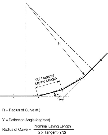
3.) Approximate radius of curve produced by a succession of 20’ lengths of pipe fully deflected.